Anudeep
Mantravadi
Skills
- Design & simulation
- SolidWorks, Siemens NX, GD&T, AutoCAD, ANSYS, OpenFOAM
- Manufacturing & hardware
- Wire arc additive manufacturing, CNC, machine shop fabrication, 3D printing, DFM/DFA
- Programming
- Python, MATLAB, C/C++, PyTorch, Linux
Leadership
- Aerospace Structures Deputy Lead, Rutgers Airborne (AIAA). Led an 18-engineer structures sub-team from requirements to flight test.
- Leg Mechanisms Lead, NASA L'SPACE NPWEE. Led the leg subteam and CAD; named co-inventor on a NASA invention disclosure.
- Mechanical Engineering Lead, RU HART. Leads a 12-engineer mechanical sub-team building Max Bot 2.0, an autonomous food delivery robot.
- CNC vertical milling certified by Rutgers University.
Micro WAAM
A wire-arc metal 3D printer built from scratch: 170+ part gantry, four-board controls, working deposition.

NASA L'SPACE
Leg mechanisms lead and named co-inventor on a NASA invention disclosure; tip-over margin up 56%.
BoneLoad LIVE
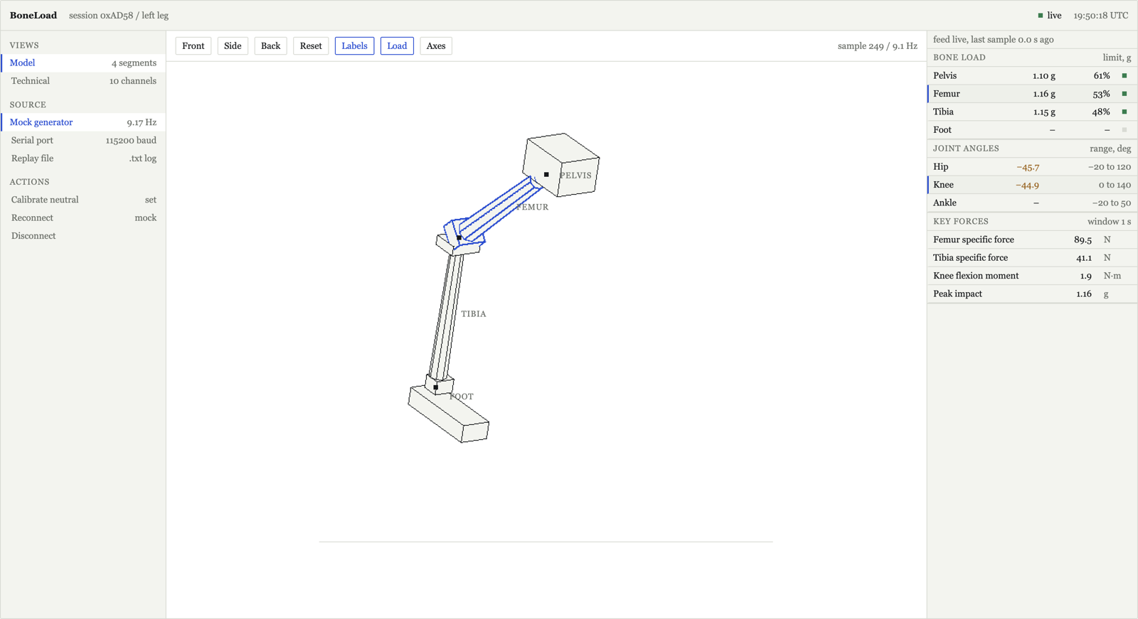
Real-time astronaut bone-load monitor from wearable sensors. Open the live demo and try it.
CFD & PINNs
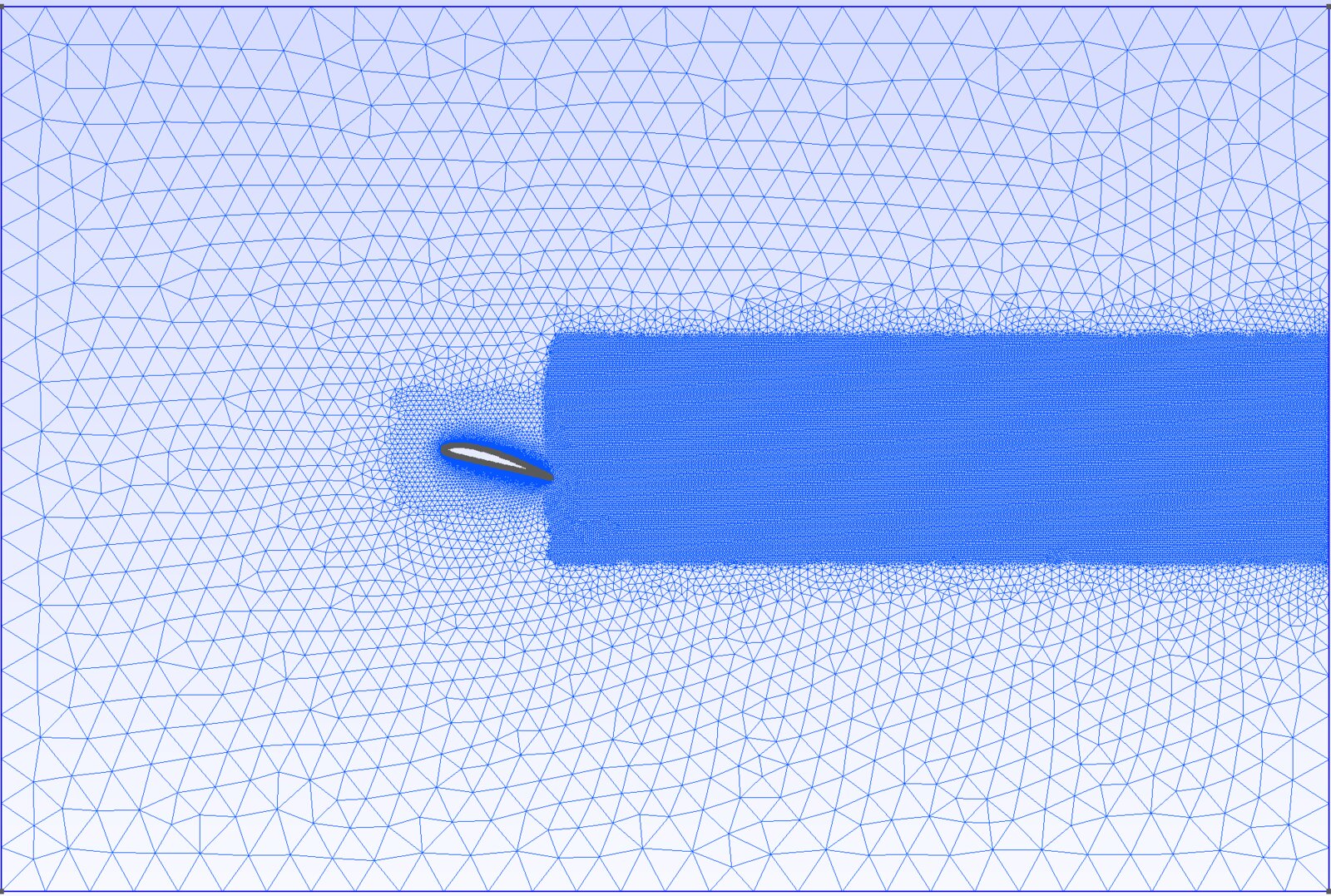
OpenFOAM validation and a forward PINN at Re=100.
AIAA Aircraft
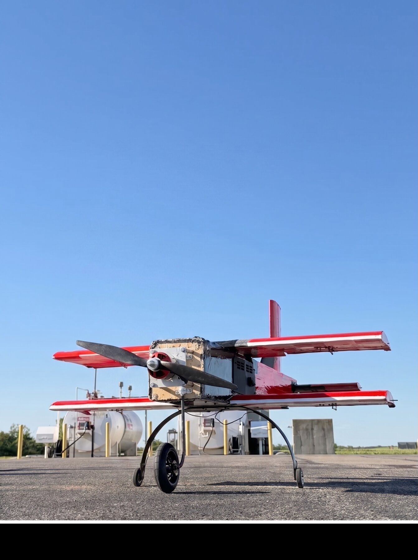
Structures deputy lead on a flown Design-Build-Fly aircraft.
Spot Inspection
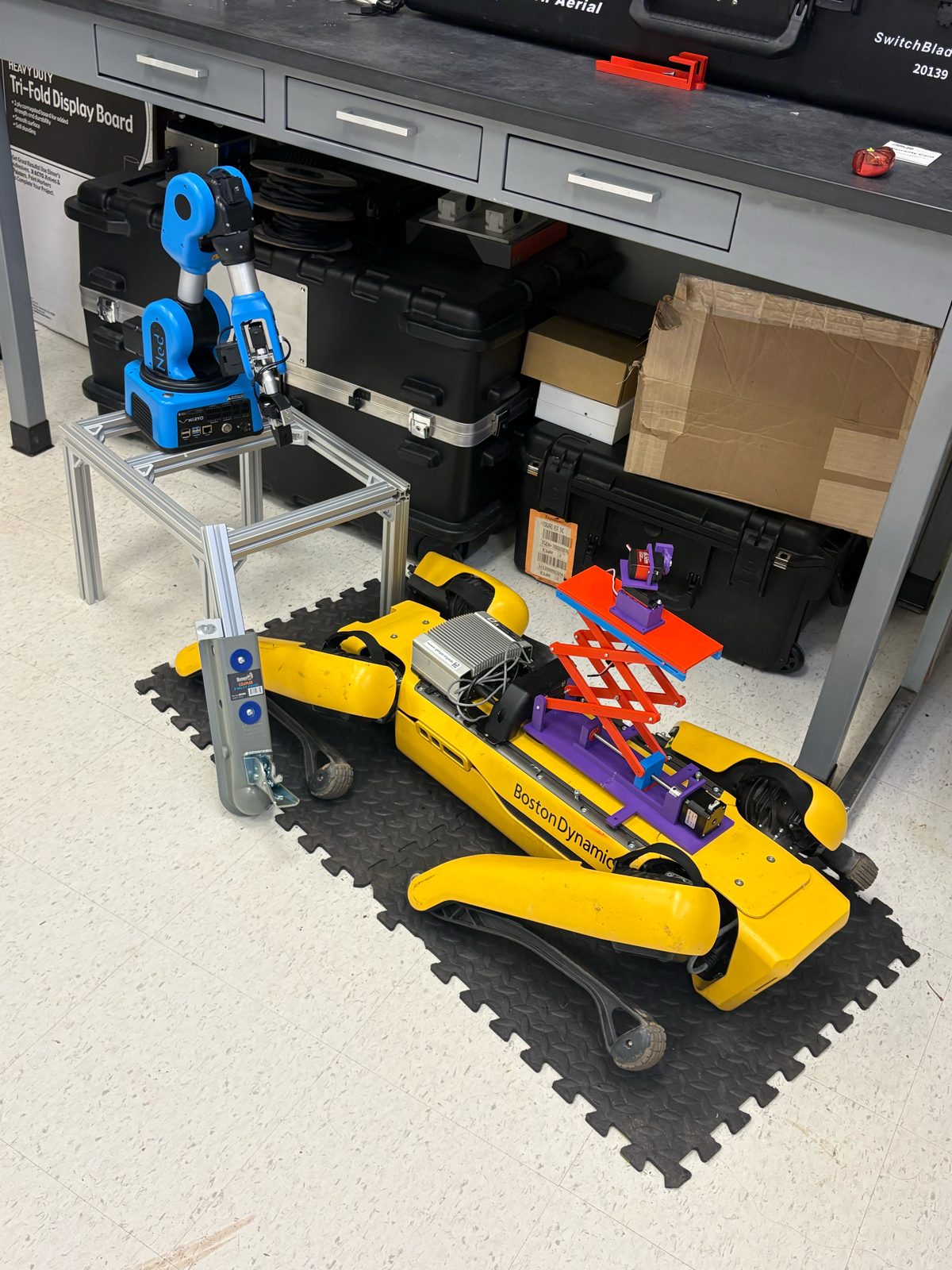
Remote inspection robot on Boston Dynamics Spot.
LUNARIS
Pipeline that ranks lunar ISRU sites from NASA orbital data.
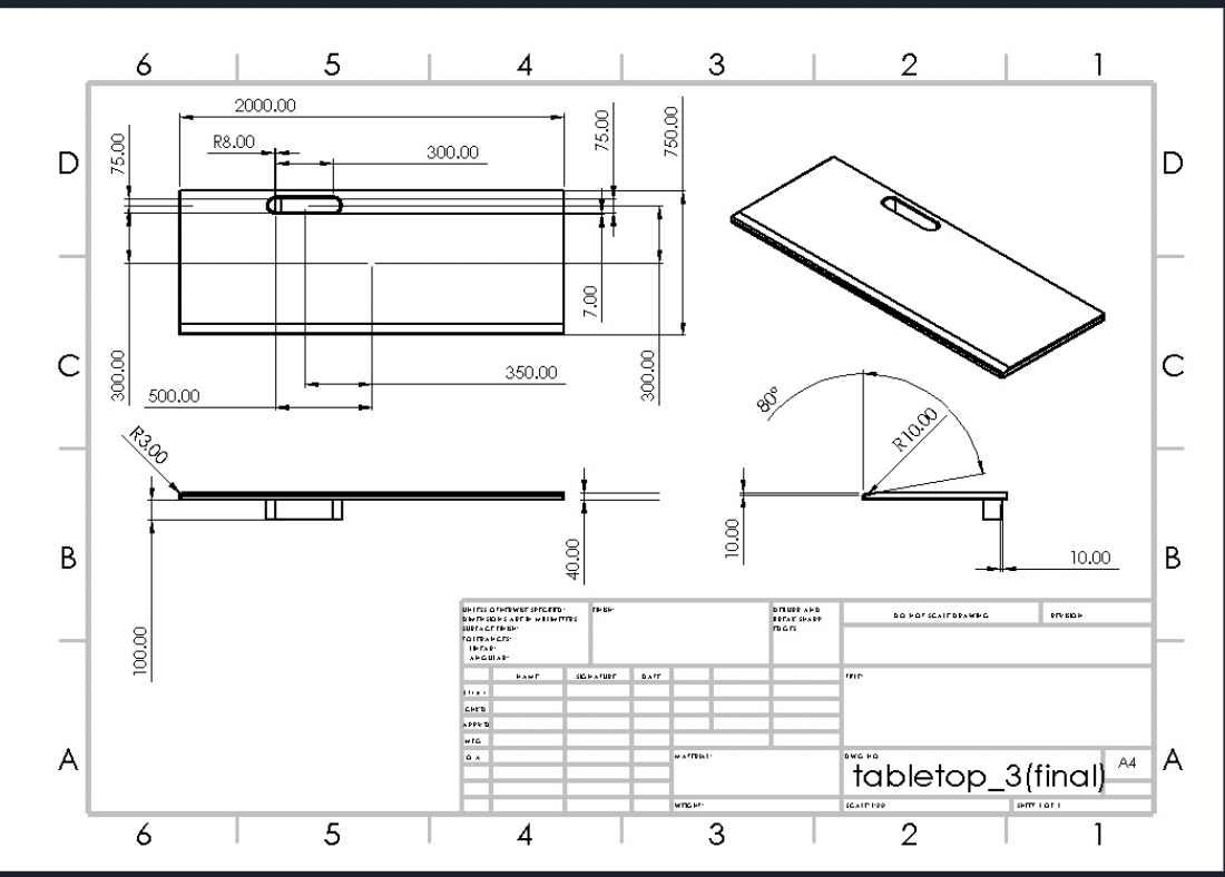
Adjustable Desk
Scissor-lift desk modeled end to end in SolidWorks.
RDE Test Rig
Cold-flow rig for rotating detonation wave dynamics.
Wind Tunnel
Adjustable-wing tunnel with pressure-based lift and drag estimates.
Micro Wire Arc Additive Manufacturing Machine
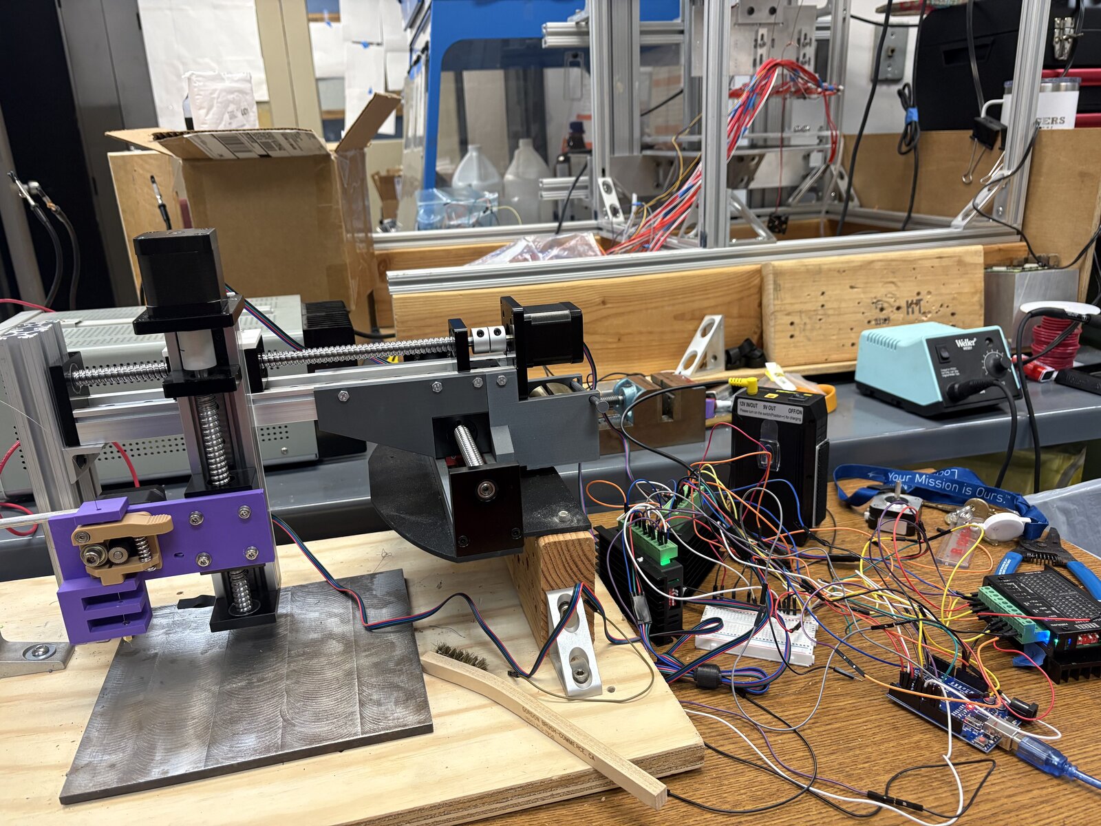
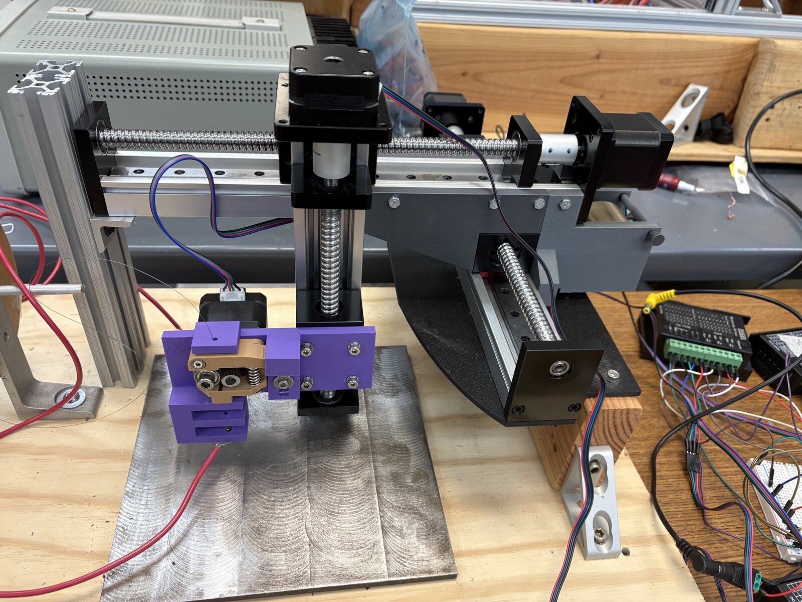
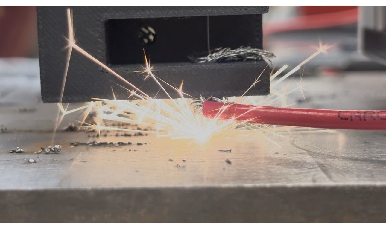
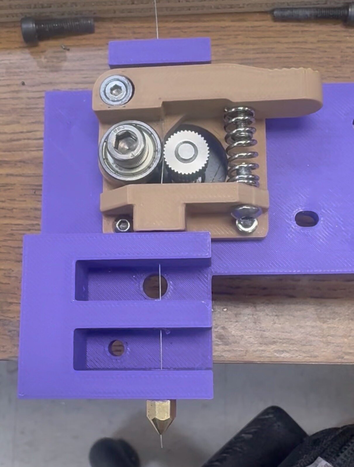
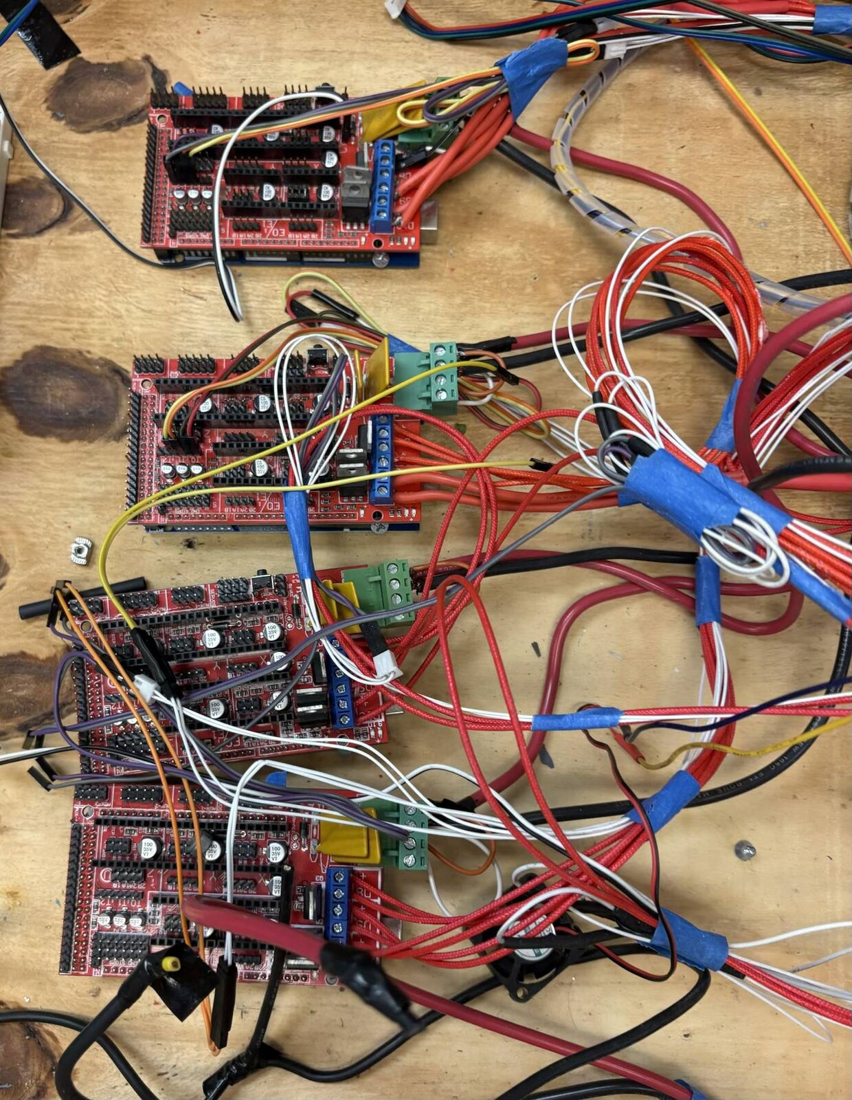
A 3D-printer-scale wire arc additive manufacturing machine built from scratch into a working deposition system. I designed the 170+ part gantry in SolidWorks, machined and assembled the moving parts, wired four RAMPS driver boards by hand, and tuned the wire feed to stay consistent through a full deposition.


National Science Foundation and the Rutgers Department of Mechanical and Aerospace Engineering
NASA Lucy Mission, L'SPACE NPWEE
Ten students and early-career engineers from eight universities wrote and costed a NASA Space Technology Mission Directorate proposal through the L'SPACE NASA Proposal Writing and Evaluation Experience (NPWEE), part of NASA's Lucy mission student pipeline. I led the leg mechanism subteam and the CAD, and was named a co-inventor on the team's NASA invention disclosure. Project details are restricted, so only outcomes are shown here.

NASA, through the L'SPACE program and the NASA Proposal Writing and Evaluation Experience (NPWEE)
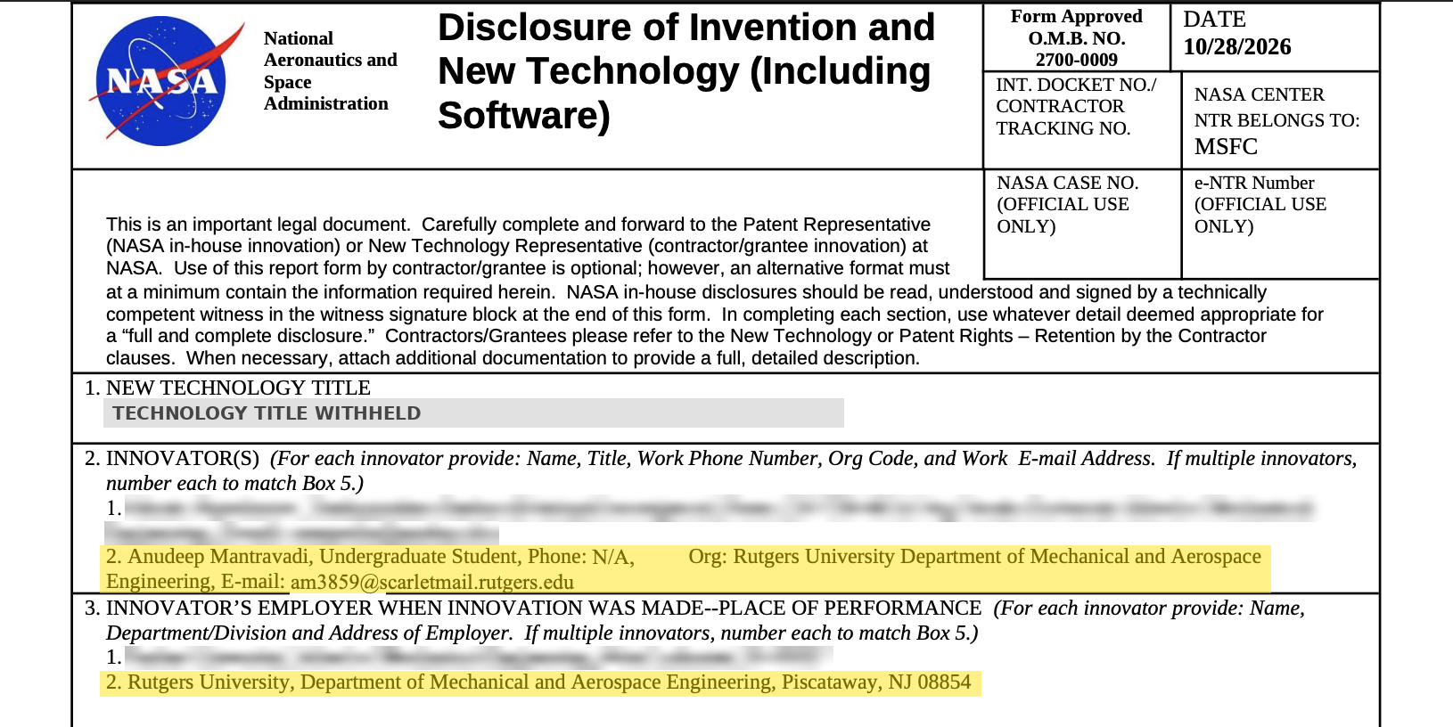
Co-invented a power-free landing leg technology featured in an official NASA New Technology Report (invention disclosure, routed to NASA Marshall Space Flight Center), credited as a named innovator for the detailed CAD design.
Targeted 10+ landings per leg versus 1 for Apollo-style single-use struts.
Raised projected tip-over margin 56% (21.6° to 33.8°) on a 20° slope by modeling the lander in Siemens NX and Fusion 360 CAD.
Delivered a drop-test-ready lander design 5.5% under NASA's $10K budget ($9,450 estimated build) by detailing the leg mechanism CAD and drawings.
CFD Validation and Physics-Informed Neural Networks
Two linked tracks. First, RANS CFD validation of a Clark Y airfoil in OpenFOAM against XFOIL. Second, a forward physics-informed neural network (PyTorch) that solves unsteady incompressible flow at Re=100 with no CFD training data. Inferring viscosity from sparse sensors with an inverse PINN is the next phase.
Rutgers Department of Mechanical and Aerospace Engineering
Gmsh mesh of about 65,000 cells around a Clark Y airfoil at 15 degrees angle of attack, refined near the airfoil and across the wake, built from scratch.
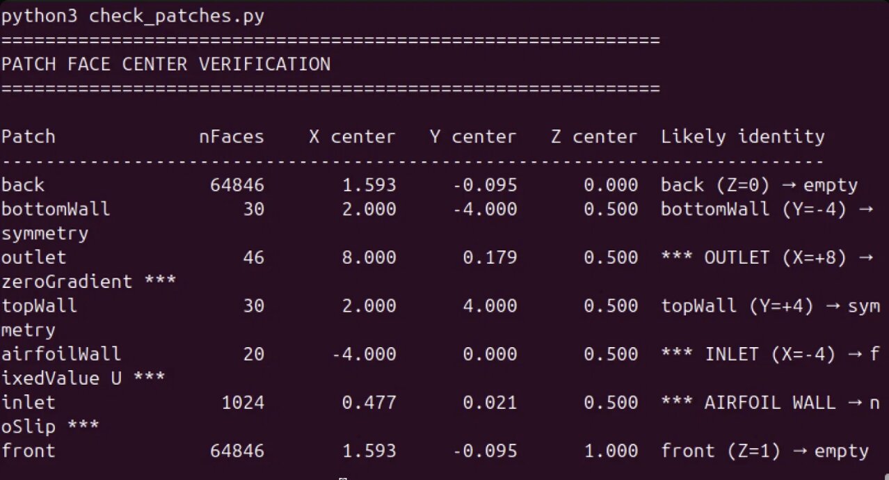
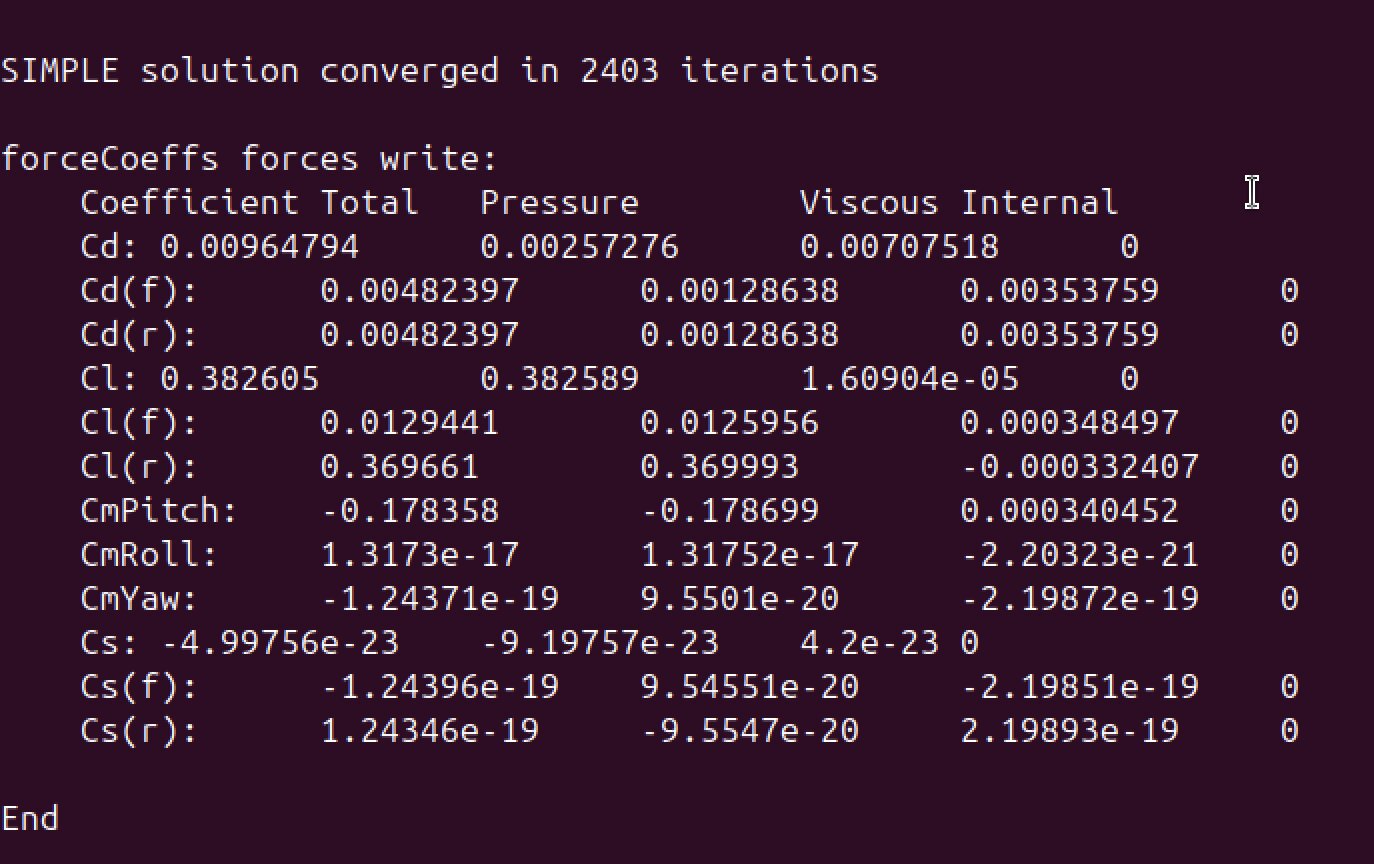
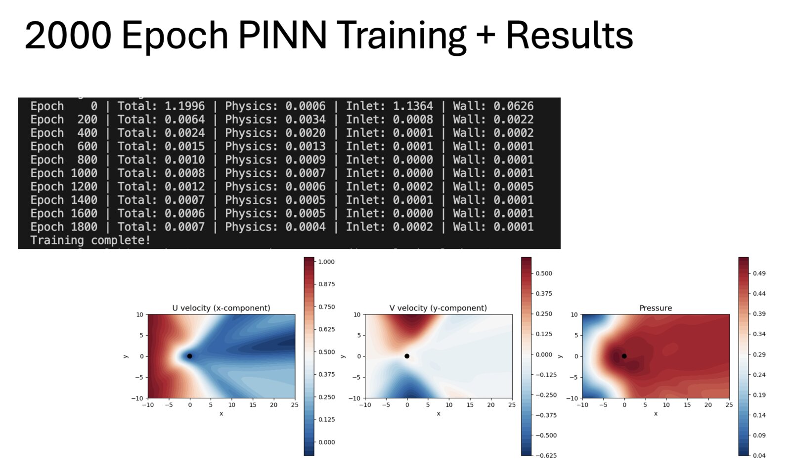
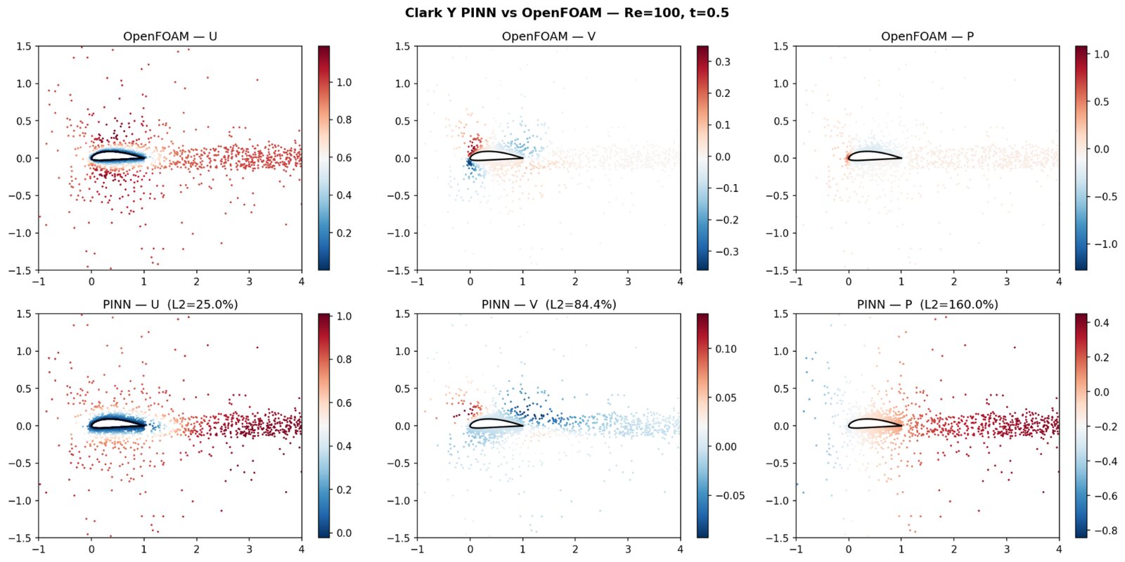
Open items: the drag mismatch against XFOIL, boundary-effect propagation, a better PINN loss function, and data density. The inverse (viscosity) PINN follows once the forward model is solid.
AIAA Design-Build-Fly: RU Airborne Aircraft
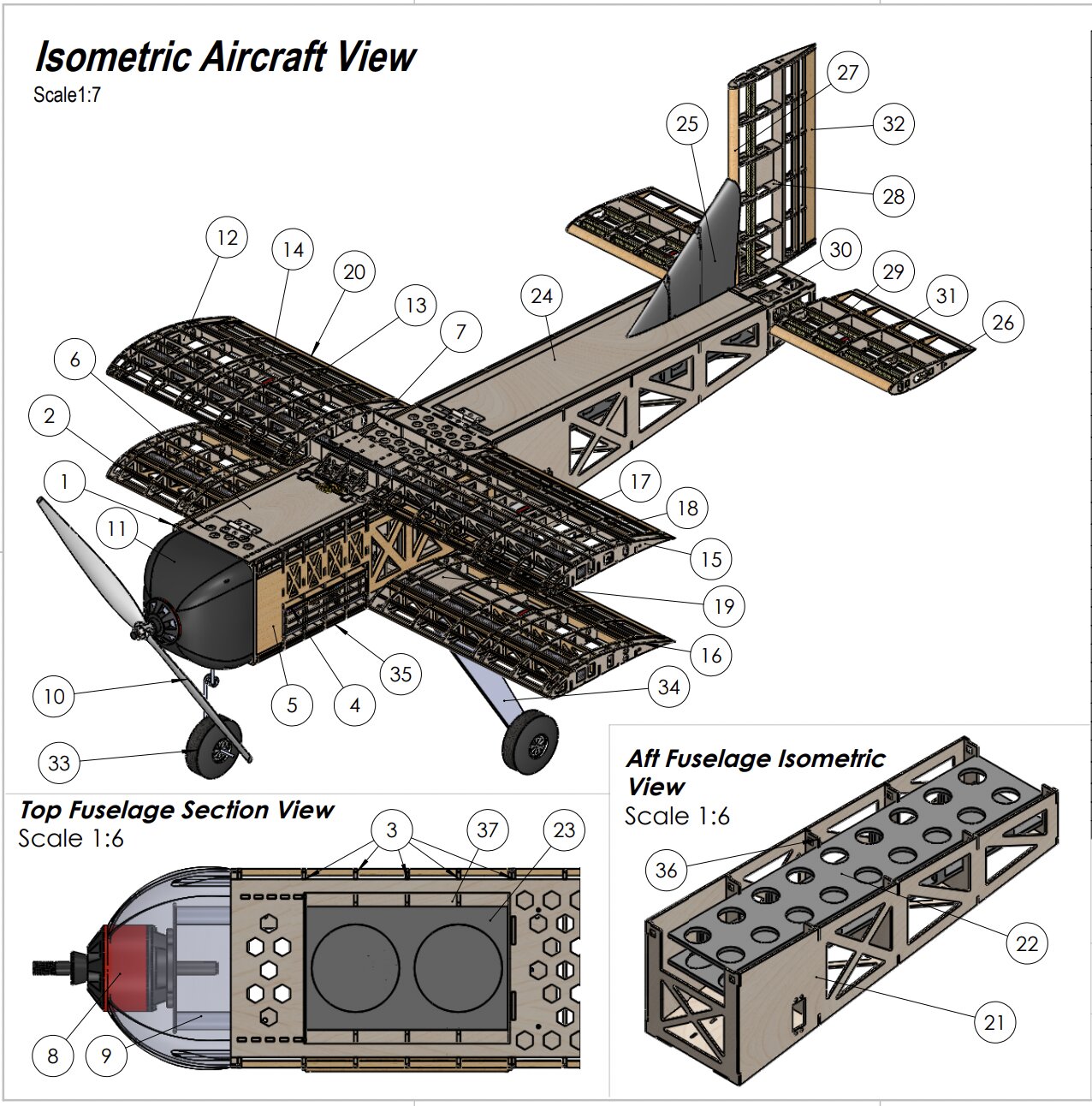
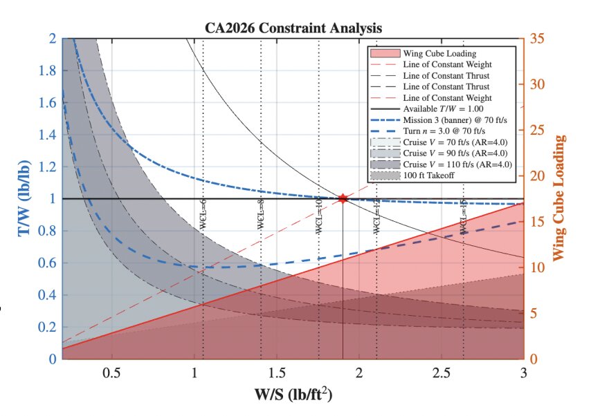
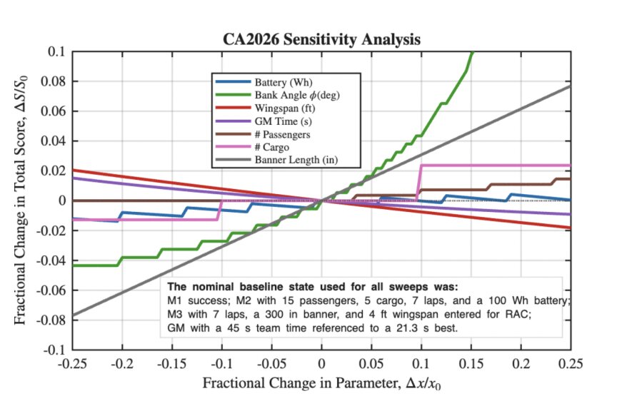
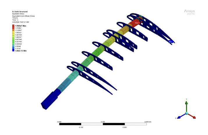
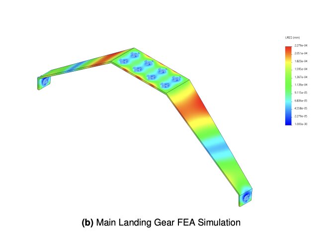
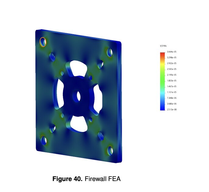
Rutgers Airborne's entry in AIAA Design-Build-Fly. Constraint and sensitivity analysis sized the airframe, and the aircraft was built and flown. As structures deputy lead I led an 18-engineer sub-team from requirements to flight test; my own CAD and FEA covered the wing spar, firewall, and landing gear.


Rutgers Airborne, competing in the AIAA Design-Build-Fly competition
The flown Design-Build-Fly aircraft. I sized it with constraint and sensitivity analysis and ran FEA on the primary load paths before fabrication.
Autonomous Inspection Robot on Boston Dynamics Spot
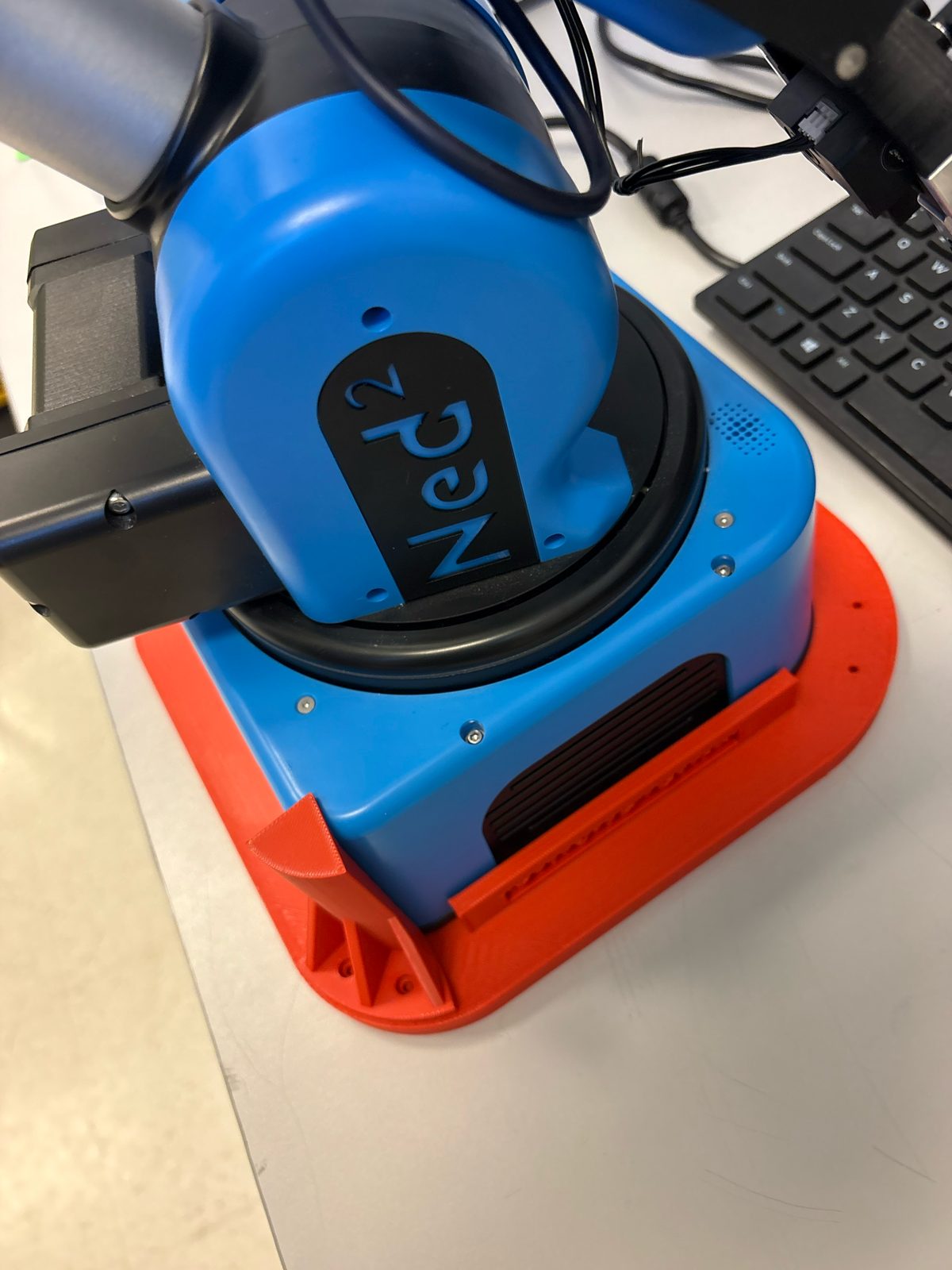
A 7-subsystem remote inspection robot on a Boston Dynamics Spot: scissor-lift sensor mast, pan-tilt thermal/RGB head, towed Niryo Ned2 arm cart, and a Jetson Orin Nano controller. Four USB cameras, a thermal camera, and temperature/humidity sensors feed a Gemini vision-language model and a UI dashboard that flags heat sources and humidity spikes.


Boston Dynamics, which sponsored the $75,000 Spot robot, and the Rutgers Department of Industrial and Systems Engineering, which funds the project
BoneLoad, Astronaut Bone-Loading Monitor
 Live demo
Try BoneLoad yourself
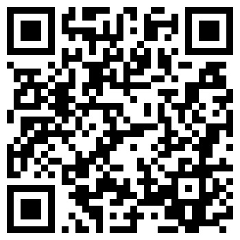
Open the real-time monitor in your browser. No hardware needed: choose the Mock generator source. Scan the code to open it on your phone.
Launch demo ↗
Built at the 2026 NASA Space Apps Challenge hosted by NYU Tandon, answering the "Create Exercise Assist Software for Astronauts" challenge. Astronauts lose roughly 1.5% of bone density per month in microgravity, so BoneLoad asks one question each day: was today's loading enough? Three body-worn accelerometers stream to an ESP32-C3 and a real-time web monitor.


NASA International Space Apps Challenge, hosted by NYU Tandon School of Engineering
Live monitor: a 3D leg model with per-segment bone load, joint angles, and estimated forces at about 9 Hz. A k-nearest-neighbors classifier (rest, walk, squat) reaches 97.8% balanced accuracy on NASA bed-rest data plus team recordings.
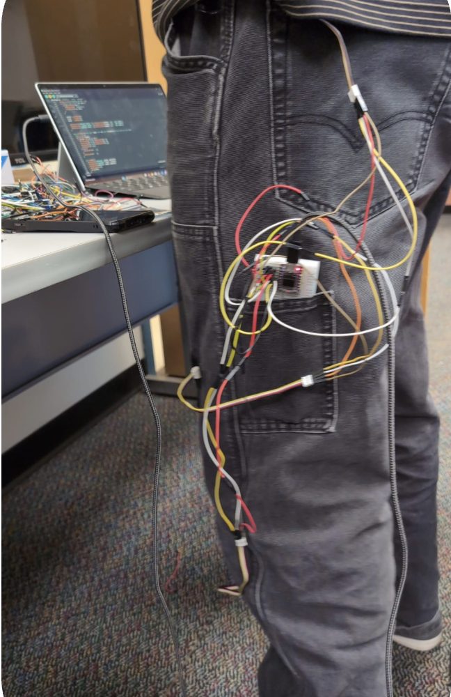
Wearable rig: belt, mid-thigh, and below-knee accelerometers on the ESP32-C3, with neutral-pose calibration turning segment tilt into joint angles.
LUNARIS: Lunar Autonomous Navigation and Resource Identification System
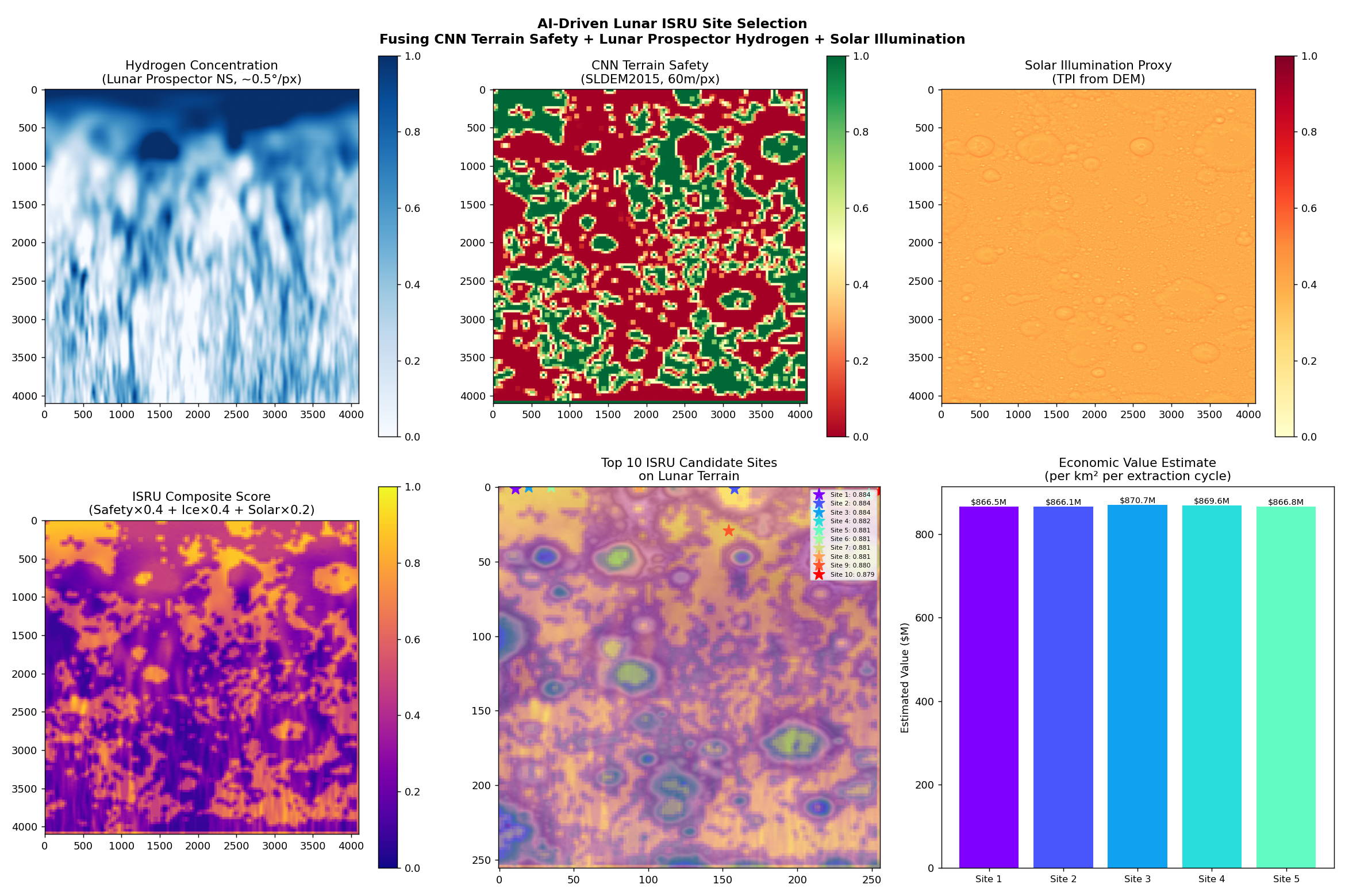
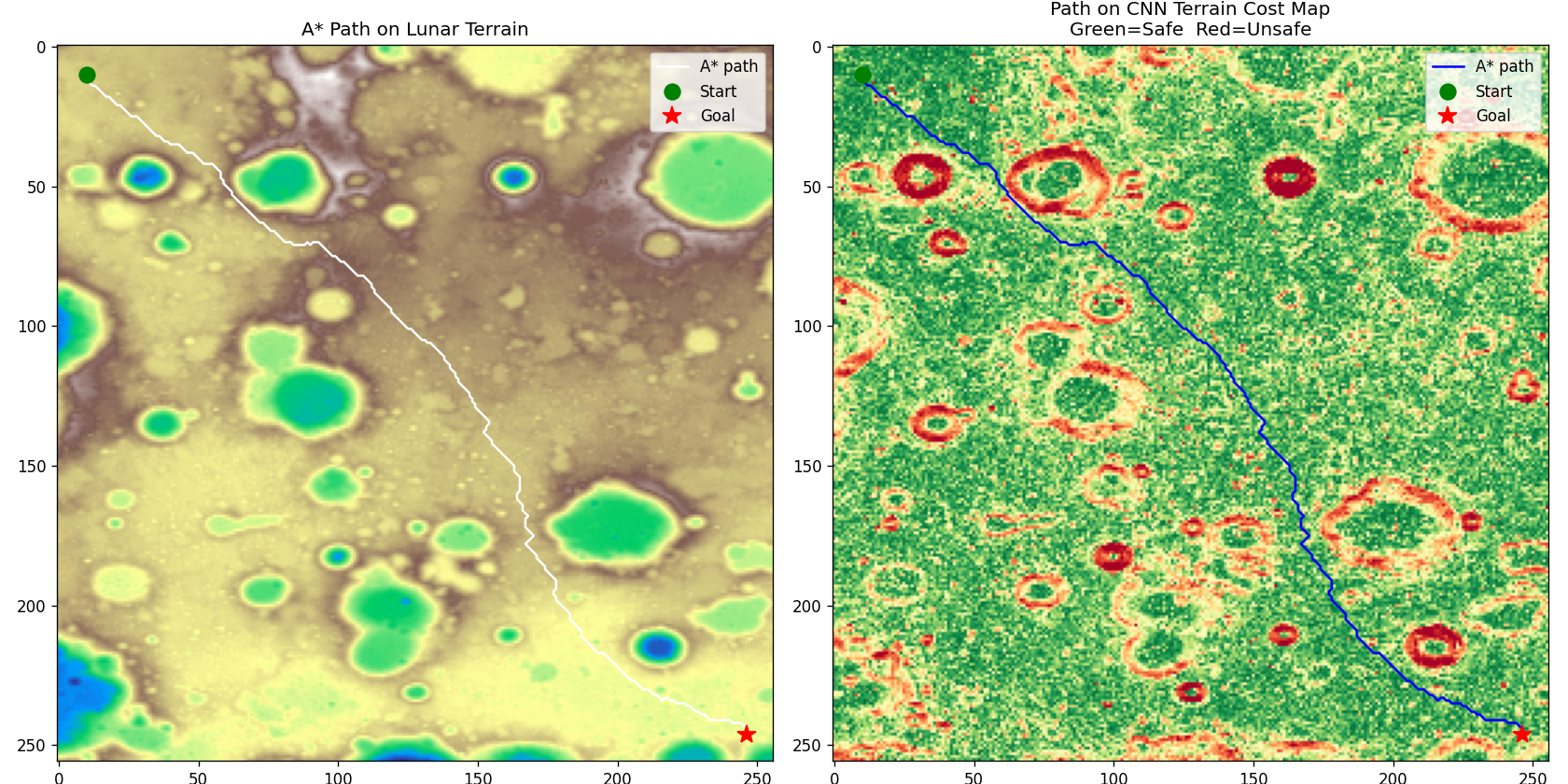
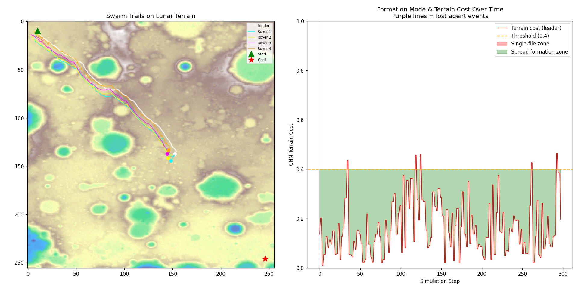
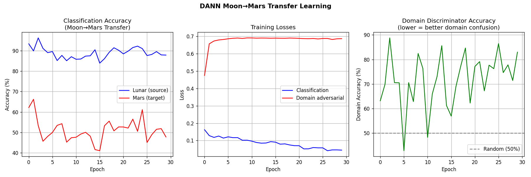
Water ice at the lunar south pole could become propellant, but choosing where to mine means fusing data from several NASA instruments by hand. LUNARIS is an open-source pipeline I built to automate that: from raw NASA orbital data to ranked candidate sites with economic valuations in under 90 seconds. It has five layers: terrain intelligence, ice probability mapping, multi-objective ISRU scoring, rover coordination, and a Moon-to-Mars transfer experiment.

Rutgers Innovation Awards
Submitted to the Rutgers Innovation Awards 2026 and NASA RASC-AL 2027.
Height-Adjustable Desk
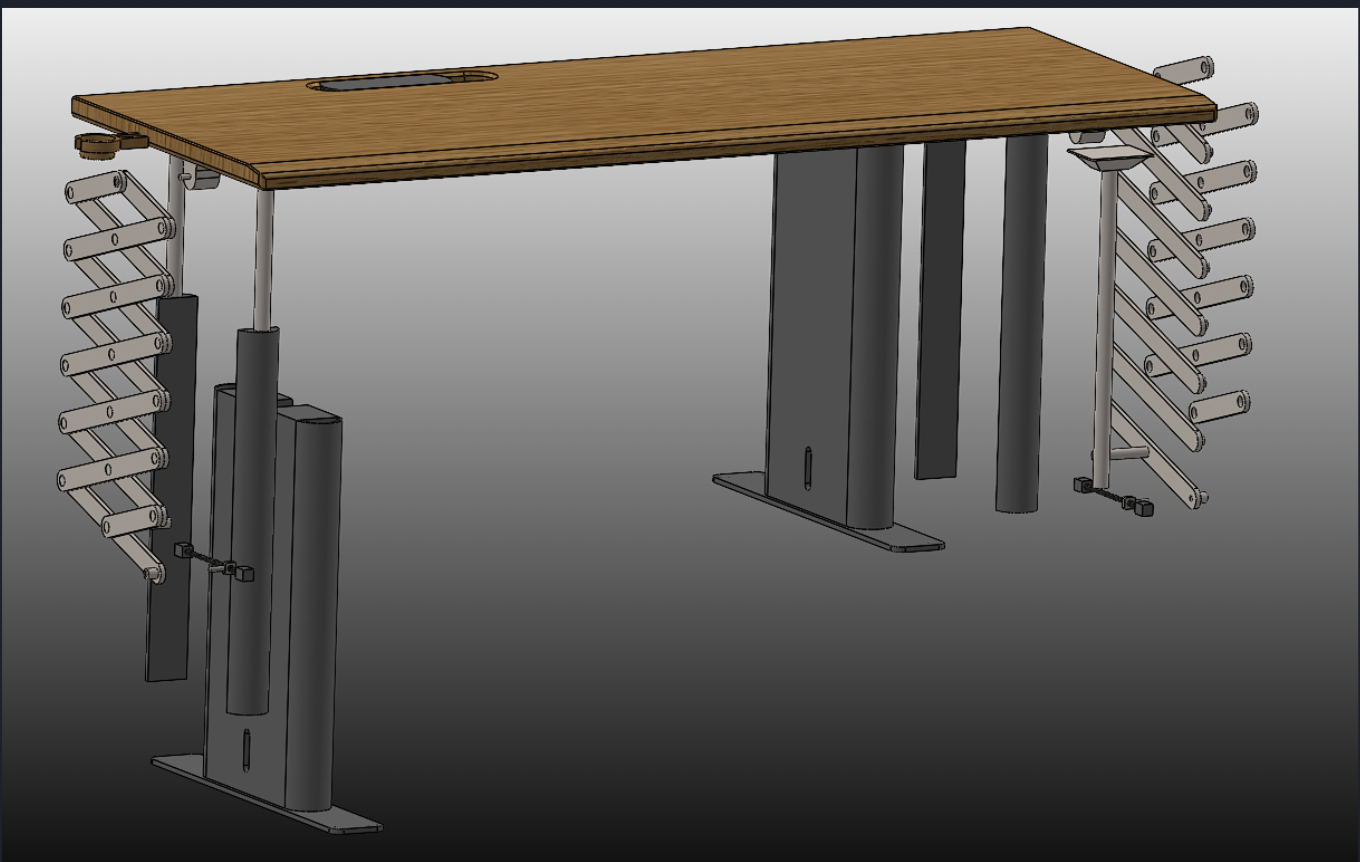
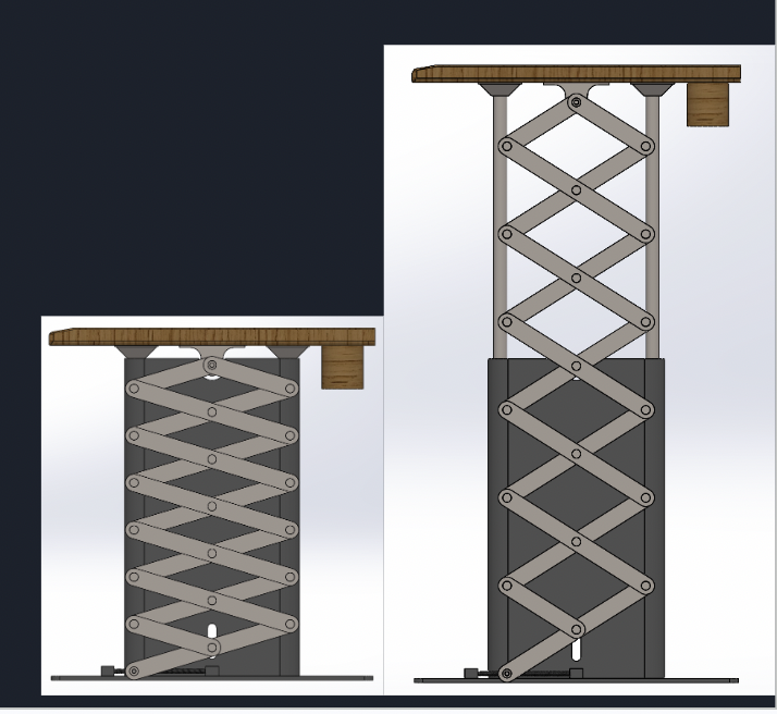
A height-adjustable desk modeled in SolidWorks around two scissor lifts driven by a linear actuator. Every fastener, bearing, and weld bead is modeled, in sheet metal and purchased hardware.
Rotating Detonation Engine, Cold Flow Test Rig
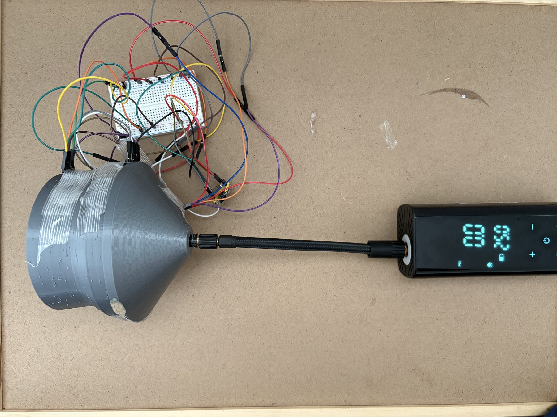
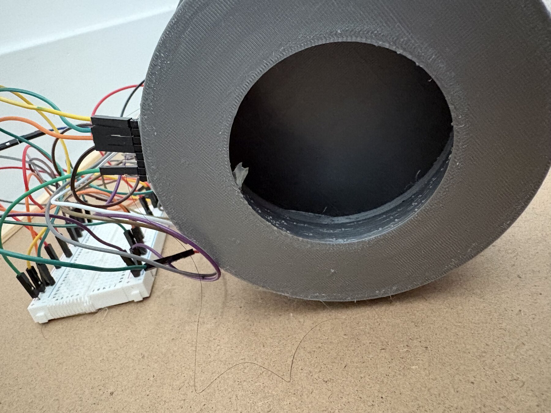
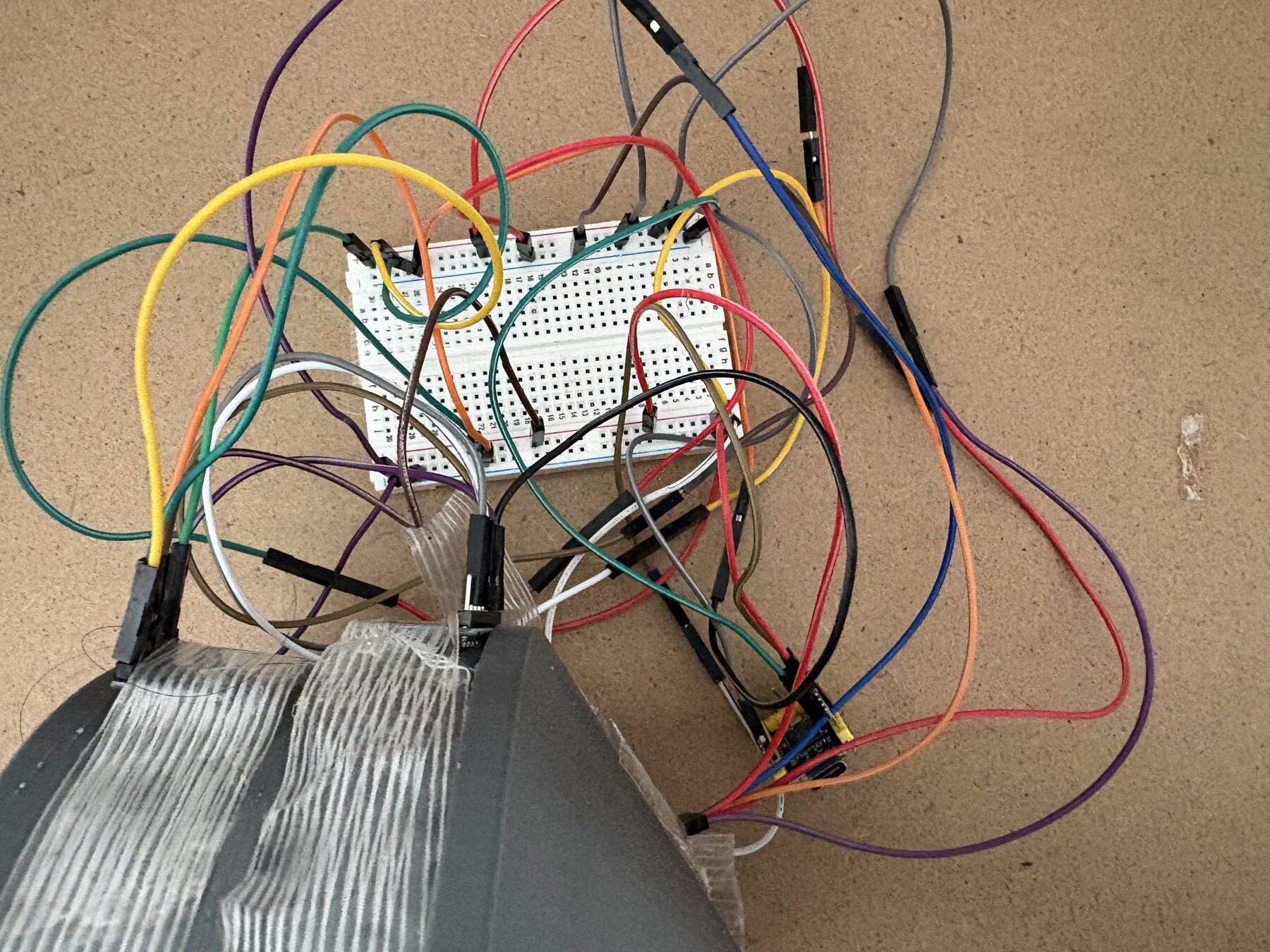
A small-scale cold-flow rig for studying rotating detonation engine wave dynamics without combustion. Compressed air passes through 12 injection holes angled at 45 degrees, which add tangential momentum and set up a rotating pressure wave in the annulus. Two MPU6050 accelerometer/gyro modules on the outer wall, one above the converging section and one below the throat, record the response from 30 to 90 PSI.
The cold-flow rig: regulated 30 to 90 PSI air supply with wireless pressure readout, a printed converging-diverging housing, and dual MPU6050 sensors logged by a Raspberry Pi Zero.
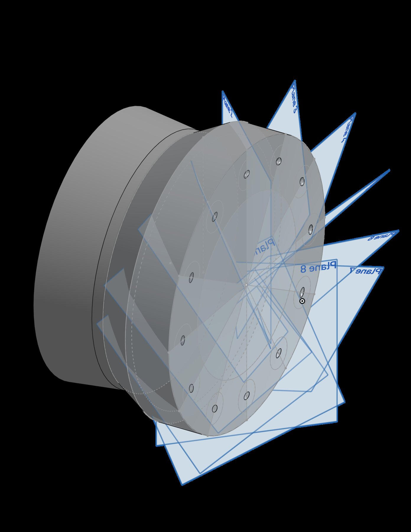
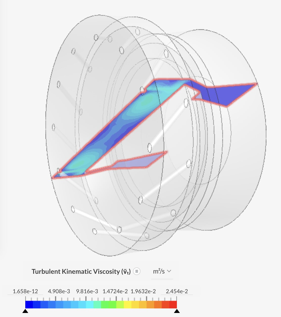
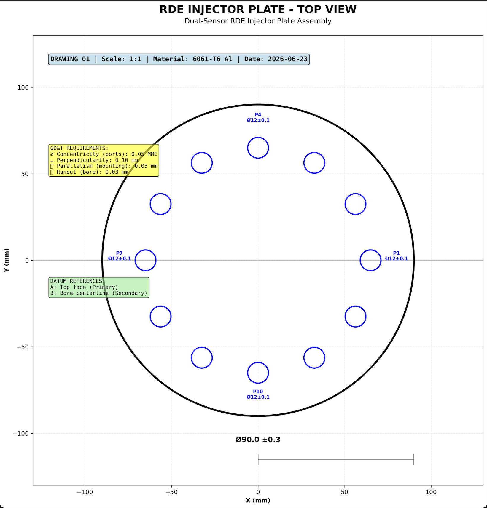
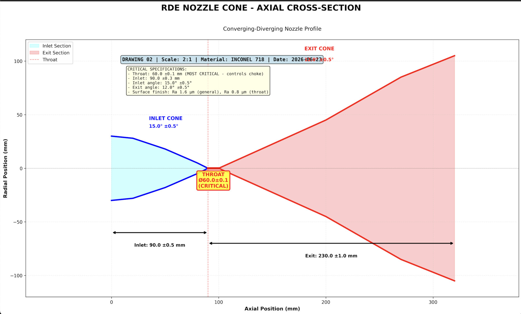
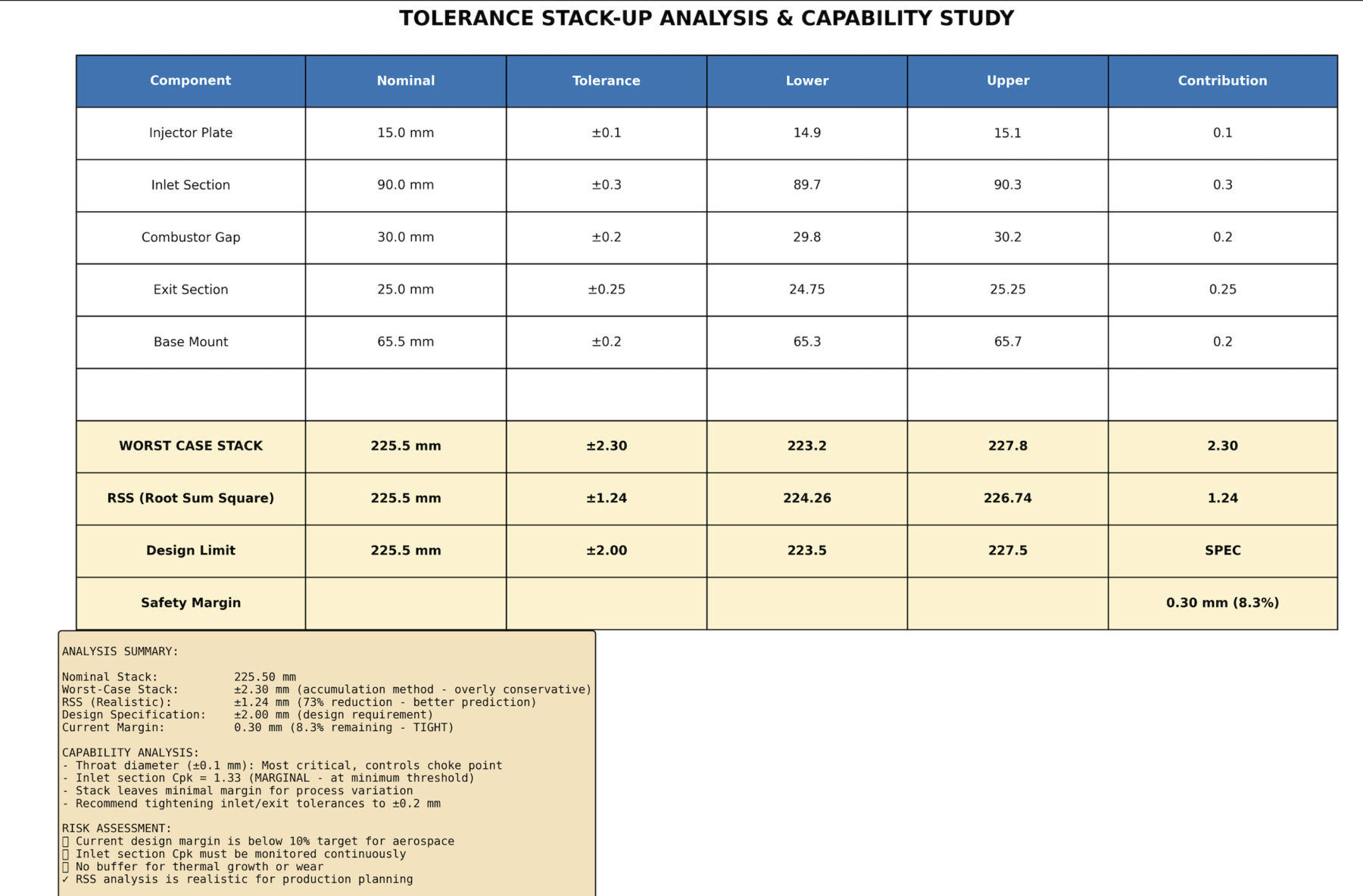
GD&T drawings for the injector plate, nozzle cone, and assembly carry worst-case stack-up analysis. The SPC control plan flagged throat diameter at Cpk 1.11, below the 1.33 target, as the dimension most likely to drift across a print run.
Adjustable Swept Wing and Wind Tunnel Test System
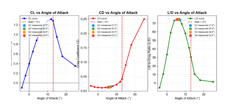
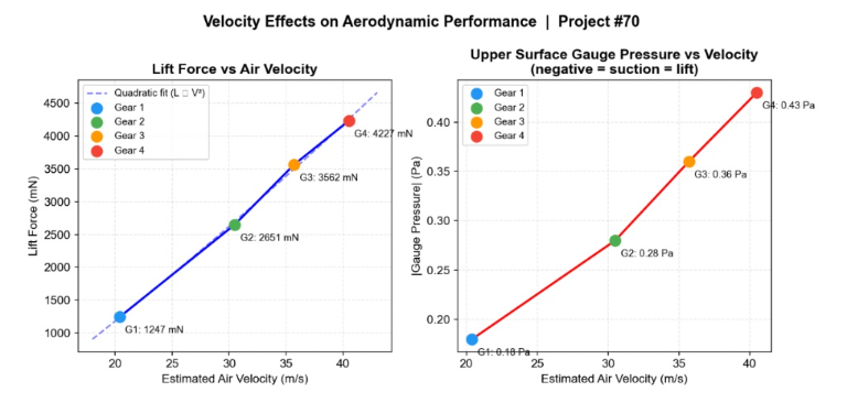
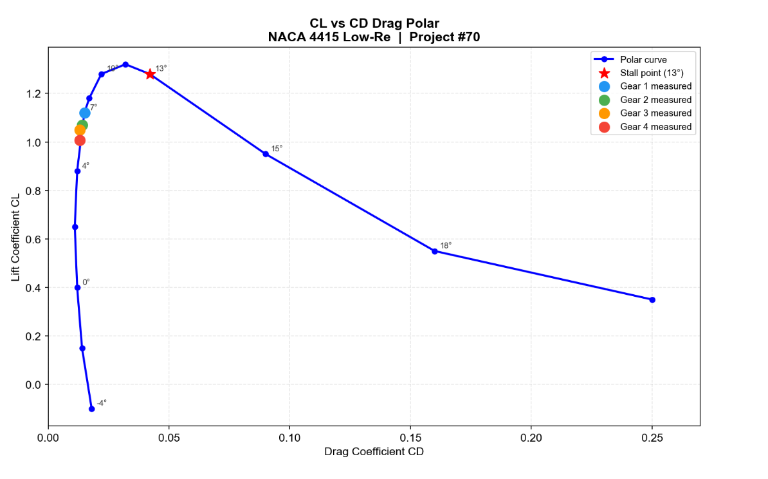
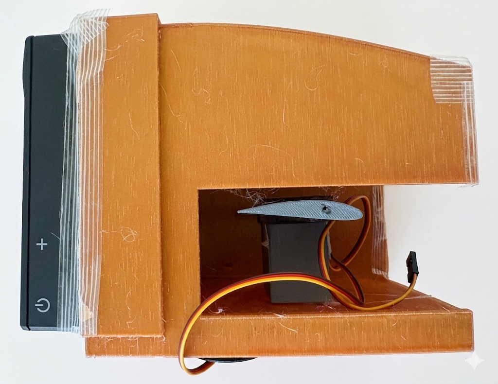
A small low-speed wind tunnel for testing a NACA 4415 airfoil. An Elegoo UNO R3 drives two synchronized MG90S servos to set angle of attack, and a BMP280 near 52 percent chord on the upper surface reads static pressure. Lift and drag coefficients are inferred from that single pressure reading, not measured with a force balance, so results are best read as trends.
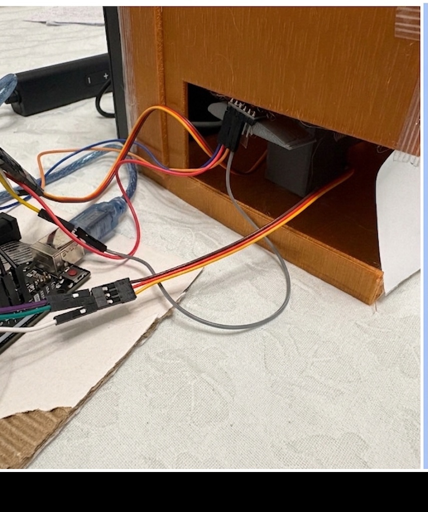
Tunnel with an adjustable NACA 4415 wing: two synchronized servos set angle of attack while the BMP280 reads surface pressure.